Share
How do I choose machining units and spindle attachments? Start by matching the operation’s required torque, speed, tool interface, radial load, coolant method, envelope, and machine-interface dimensions—not by choosing the attachment with the highest advertised rpm. For how to choose CNC machining units, compare the workpiece material, hole diameter, cutting speed, spindle power, and cycle time. For spindle attachments for CNC machines, verify taper compatibility, allowable runout, transmission efficiency, and balance grade. A reliable modular machining unit selection process uses measured cutting forces, ISO 230 inspection methods, and a trial cut before production approval.

Users usually face one of four practical problems:
The correct solution depends on the operation. A right-angle head is normally selected for access to a side face. A high-speed spindle attachment is intended for small-diameter cutters or miniature drilling. A geared multiplier can increase speed but may reduce available output torque. A drilling or tapping unit may prioritize axial thrust, rigidity, and synchronized motion rather than maximum rpm.
HAEGOLIA buyers should therefore treat the attachment as part of the complete machining system: CNC control, machine spindle, toolholder, cutting tool, coolant delivery, workholding, and inspection equipment must all be compatible.
| Operation | Typical attachment type | Primary selection criteria | Typical failure if mismatched |
|---|---|---|---|
| Side-face milling | Right-angle head | Output torque, radial stiffness, angular accuracy, clearance | Chatter, poor squareness, cutter deflection |
| Small-hole drilling | High-speed spindle attachment | Maximum rpm, balance, runout, bearing temperature | Drill wandering, heat generation, premature bearing wear |
| Large-hole drilling | Geared drilling unit | Output torque, thrust capacity, gearbox rating, coolant access | Spindle overload or stalled tool |
| Rigid tapping | Tapping unit or synchronous tapping attachment | Pitch synchronization, torque control, axial compliance | Broken tap or incorrect thread pitch |
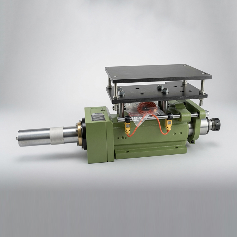
| Several holes in one cycle | Multi-spindle drilling unit | Spindle spacing, simultaneous thrust, chip evacuation | Uneven hole position or overloaded machine axis |
Before requesting a quotation, prepare a one-page application sheet containing:
For milling, calculate spindle speed using:
where
For milling feed:
where
Confirm every mechanical interface from the machine spindle to the cutting tool:
Do not assume that two holders with the same nominal taper are interchangeable. The taper angle, flange geometry, pull stud, gauge length, key orientation, and automatic tool-change clearance must all match the machine builder’s specification.
Power and torque are related by:
where
Compare three different ratings:
For tapping, torque capacity is particularly important. The theoretical tapping torque varies with material, thread size, tap geometry, lubrication, and hole preparation. Use the tap supplier’s torque chart rather than estimating from motor power alone.
Runout directly affects hole size, cutter loading, surface finish, and tool life. Specify where runout is measured: at the attachment nose, toolholder taper, collet, or a defined distance from the gauge line. A value measured at 100 mm from the spindle nose is not directly comparable with one measured at 20 mm.
For high-speed applications, request the balancing condition and balancing standard. ISO 21940-11 classifies balancing quality for rotors; the correct balance grade depends on speed, rotor mass, and application. The attachment supplier should state the tested speed and residual unbalance rather than using the phrase “high precision.”
For general production qualification, inspect:
Prepare the following before technical discussions with HAEGOLIA or another attachment supplier:
Use calibrated equipment where possible:
Inspection and test records should identify the instrument serial number, calibration status, ambient temperature, measurement location, attachment serial number, and operator. ISO 230-1 addresses machine-tool geometric accuracy testing, while ISO 230-2 covers positioning accuracy and repeatability testing. These standards do not replace the attachment supplier’s acceptance specification, but they provide a recognized framework for machine-tool verification.
Tools: part drawing, process plan, CAD model, cutting-tool catalogue.
Action: Mark whether the attachment will drill, tap, mill, bore, grind, or simply provide access to a different face. Select one dominant operation for initial sizing.
Parameters: record tool diameter, depth of cut, hole depth, thread pitch, cutting speed, feed, and required cycle time.
Check: confirm that the operation cannot be completed safely with the existing spindle and a standard holder.
Failure fix: if the only reason for an attachment is tool-access difficulty, evaluate a different fixture orientation or a fourth-axis setup before adding transmission components.
Tools: spindle drawing, caliper, gauge blocks, taper gauge, machine manual.
Action: measure or verify the taper, flange, pull stud, key slot, gauge length, and tool-change envelope.
Parameters: record spindle taper designation, maximum tool mass, allowable tool length, automatic tool-change stroke, and orientation repeatability.
Check: perform a dry tool-change test at reduced speed with the machine disabled from cutting.
Failure fix: stop if the attachment contacts the changer arm, enclosure, table, rotary axis, or workpiece. Obtain a revised gauge length or a different body design; do not remove safety covers to create clearance.
Tools: cutting-data sheet, calculator, spindle power curve.
Action: calculate required rpm and feed, then determine whether the machine and attachment can provide the required output torque continuously.
Parameters: compare required rpm with continuous rated rpm, required torque with continuous torque, and calculated feed with the machine axis-feed limit.
Check: include transmission efficiency, acceleration time, interrupted cutting, tool engagement, and the heaviest expected workpiece condition.
Failure fix: if torque is insufficient, reduce cutter diameter or radial engagement, select a lower-ratio attachment, change the cutting tool, or use a more powerful machine. Do not solve a torque shortage by exceeding the attachment’s rated load.
Tools: calibrated test indicator, precision test bar, tool presetter, clean lint-free cloth.
Action: clean the taper and toolholder, install the attachment, mount a certified test bar or reference tool, and measure radial and axial runout at the specified distance.
Parameters: use the tolerance required by the drawing and tool manufacturer. The supplier must state its own acceptance value and measurement location.
Check: rotate the spindle slowly by hand or with the machine’s approved inspection function. Repeat the measurement after removing and reinstalling the attachment to assess repeatability.
Failure fix: if runout changes after cleaning and reseating, inspect the taper, pull stud, key, toolholder, and spindle nose. Replace damaged components; do not compensate for mechanical damage with tool offsets.
Tools: coolant-flow meter, pressure gauge, chip-control data, enclosure inspection checklist.
Action: verify whether coolant reaches the cutting edge through the tool, through the attachment, or through an external nozzle.
Parameters: record coolant pressure, flow rate, filtration level, tool passage diameter, and maximum allowable pressure for the attachment.
Check: run coolant without cutting and confirm that the stream does not leak into the attachment bearings or miss the hole entrance.
Failure fix: use an approved sealing arrangement, external delivery, peck drilling, or a tool with internal coolant. Never drill through a blocked coolant passage or exceed the attachment’s pressure rating.
Tools: production material, new cutting tool, vibration meter, temperature device, inspection gauges.
Action: machine a representative feature using the tool supplier’s starting data. Increase load only after the first cut is stable.
Parameters: record rpm, feed, depth of cut, radial engagement, coolant pressure, cutting time, spindle load, vibration, temperature, and tool wear.
Check: inspect size, position, cylindricity, perpendicularity, surface roughness, burr formation, and tool edge condition.
Failure fix: adjust only one variable at a time. For chatter, first reduce overhang and radial engagement, then alter rpm or feed according to the tool supplier’s guidance. For heat, verify coolant, tool wear, bearing temperature, and excessive rubbing.
Tools: first-article report, control plan, maintenance log, serial-number record.
Action: document the approved tool, offsets, cutting data, inspection results, and maintenance intervals.
Parameters: define allowable runout, maximum speed, maximum torque or spindle-load limit, bearing-temperature limit supplied by the manufacturer, lubrication interval, and replacement criteria.
Check: repeat the trial on the actual machine and with the actual workholding arrangement. Keep the acceptance report with the attachment serial number.
Failure fix: quarantine the attachment if inspection results drift, abnormal noise develops, or repeatability falls outside the approved limit. Investigate spindle taper cleanliness, bearing condition, toolholder wear, and machine alignment before returning it to service.
For safety and accuracy, use original technical documents rather than unverified marketplace claims. Relevant references include ISO 230-1 for machine-tool geometric tests, ISO 230-2 for positioning accuracy and repeatability, ISO 21940-11 for rotor balancing quality, ISO 1940-1 where legacy balancing documentation is encountered, and ISO 16089 for safety considerations associated with stationary grinding machines. The applicable machine-tool, attachment, toolholder, and cutting-tool manuals remain mandatory for product-specific limits.
Published manufacturer case studies are useful only when they identify the machine, material, tool, cutting data, and measured result. A case study that says an attachment “improved productivity” without reporting cycle time, tool life, dimensional results, and test conditions is not enough to justify a purchase. When evaluating a HAEGOLIA proposal, request a drawing, rated input and output data, runout test location, balancing condition, coolant limit, maintenance requirements, and a sample acceptance report.
A responsible purchasing decision should be based on a documented trial rather than an anecdotal claim. If a supplier presents a customer case, verify the original publication or obtain customer-approved test records before treating the result as transferable to your material, machine, and tool geometry.
A high-speed attachment may be suitable for a 3 mm cutter but unsuitable for a large drill. Check the torque curve and output rating at the actual operating speed. If the attachment is used below its efficient speed range, the process may produce rubbing, chatter, or overload.
Every additional millimetre of overhang increases deflection sensitivity. Check the complete assembly—from machine spindle to cutting edge—during tool change, rapid traverse, rotary-axis movement, and enclosure operation.
Always record the measurement distance. A runout value at the nose cannot be compared directly with one measured at the end of a long test bar.
Side drilling and deep-hole drilling may require a directed coolant stream or through-tool delivery. Verify passages, seals, pressure limits, and chip evacuation before production.
An attachment changes the tool assembly’s mass, centre of gravity, and inertia. Confirm the machine’s tool-change capacity and reduce rapid-axis acceleration if required by the machine builder or process validation.
If the fixture allows the workpiece to move, a more rigid spindle attachment will not solve the dimensional problem. Measure fixture displacement, clamping force, and datum repeatability before changing the spindle system.
Purchase price is only one part of the decision. Estimate total cost using:
Use measured production data. For example, compare the existing and proposed process using cycle time per part, tool changes per batch, first-pass yield, mean hole-size variation, surface roughness, and unplanned stoppage hours. Avoid claiming a percentage improvement until those values have been recorded under comparable conditions.
Choose the machining unit or spindle attachment only after confirming:
The shortest route to a reliable purchase is to send HAEGOLIA a complete application sheet and request a technical proposal tied to your machine model and part drawing. The final approval should come from measured torque demand, taper compatibility, runout, cutting-test results, and inspection data—not from adjectives such as “powerful,” “rigid,” or “high precision.” This evidence-based approach to how to choose CNC machining units, spindle attachments for CNC machines, and modular machining unit selection keeps torque, runout, taper interface, live tooling, right-angle heads, and multi-spindle drilling units aligned with the actual production requirement.