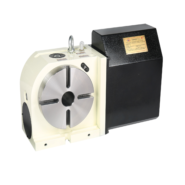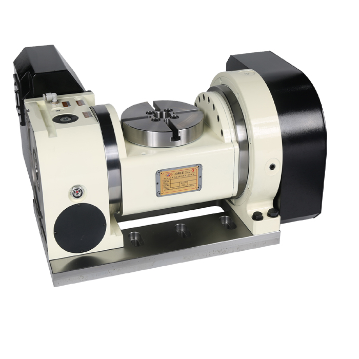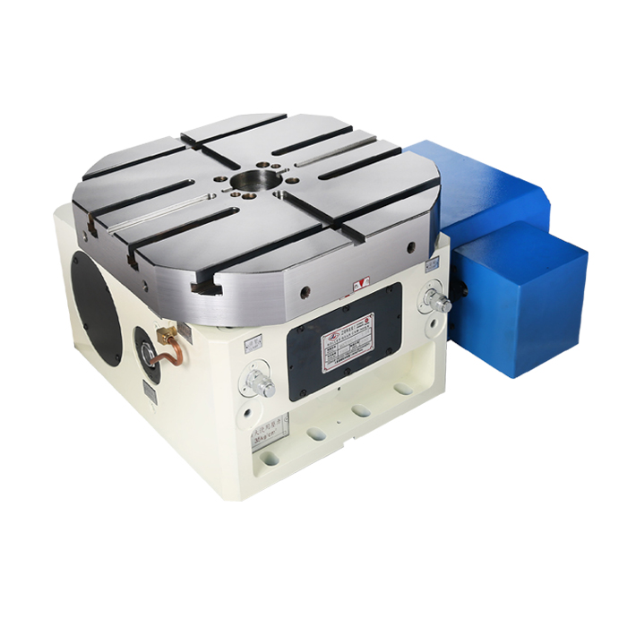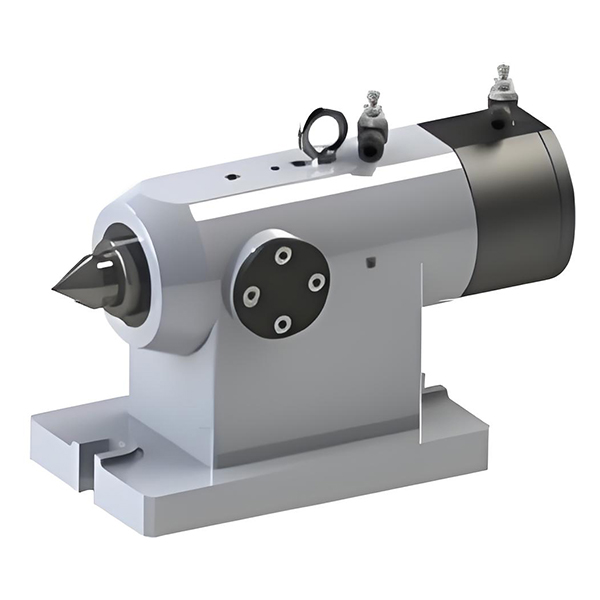
Choosing the best workholding method for CNC milling is not simply a matter of selecting the strongest clamp. A machinist comparing a vise vs chuck for CNC machining or choosing collets for precision turning must balance access, part geometry, setup time, repeatability, and deformation risk. In practical CNC workholding, a jaw chuck, modular fixture, accurate datum, measured runout, and available clamping force determine whether the process remains stable from the first part to the last. The right choice depends on the workpiece and cutting forces, not on the label attached to the tool.

Why Workholding Selection Matters in Clamping Systems for CNC Machining
A workholding device performs three jobs at the same time: it locates the workpiece, resists cutting forces, and allows the cutting tool to reach the required surfaces. If any one of these functions is weak, the machine may still complete a cycle while producing chatter, dimensional drift, burrs, poor surface finish, or a part that moves during machining.
The consequences are measurable. A 0.02 mm positioning error can consume most of a 0.05 mm machining tolerance before tool wear, thermal growth, and material variation are considered. A workpiece that lifts 0.03 mm above a vise jaw can create a corresponding error on a milled face, even when the machine itself is correctly calibrated. Likewise, a chuck with 0.05 mm indicated runout can transfer that error directly to a turned diameter unless the part is machined in a later operation or the chuck is adjusted.
For this reason, product evaluation should include more than advertised holding force. Review the actual contact area, jaw condition, repeatability, accessible tool paths, maximum allowable speed, coolant exposure, maintenance requirements, and the time required to load and verify each part. A device that costs less but adds three minutes to every setup may be more expensive over a 500-part order than a higher-priced fixture that reduces loading time and inspection frequency.
How to Match CNC Workholding to the Part and Process
Begin with the manufacturing process rather than the workholding catalog. Record the material, stock dimensions, finished dimensions, number of operations, cutting-tool diameter, radial and axial depth of cut, spindle speed, feed rate, tolerance, surface-finish requirement, and the surfaces that must remain accessible.
Workholding and Clamping Systems for CNC Machining: The Six-Question Review
- What is the primary machine? A three-axis mill, five-axis machining center, CNC lathe, Swiss-type lathe, grinder, or inspection machine creates different access requirements.
- What is the workpiece shape? Rectangular blocks usually suit vises; round bar often suits chucks or collets; thin, irregular, or previously machined parts may need a dedicated fixture.
- Where is the locating datum? The workholding system should establish the same reference surfaces used in the drawing and inspection plan.
- How large are the cutting forces? Estimate the tangential force and the friction available at the contact surfaces rather than relying on a generic force rating.
- How many parts will be produced? A manual vise may be appropriate for one prototype, while a repeat production run may justify a quick-change, pneumatic, hydraulic, or multi-part fixture.
- How often must the part be repositioned? A single setup reduces cumulative datum errors and usually improves consistency, provided the fixture exposes all required surfaces.
For an initial force check, cutting power can be related to tangential cutting force with the approximate relationship F = P / v, where F is force in newtons, P is cutting power in watts, and v is cutting speed in meters per second. This is only a first estimate because actual force depends on material, tool geometry, chip thickness, engagement, and machine efficiency. The holding system must also resist overturning moments, not only straight-line movement.
For example, if a milling operation produces an estimated 1,200 N lateral force and the effective friction coefficient between the workpiece and jaws is 0.2, a simple friction-only estimate requires at least 6,000 N of normal clamping force before applying a safety factor. Real designs also use positive steps, serrated jaws, locating pins, or form features so that friction is not the only method resisting movement. Never treat this example as a universal setting for a specific vise or material.
Vise Workholding for CNC Milling and Prismatic Parts
A machine vise is usually the most practical starting point for rectangular, square, or moderately irregular parts. The fixed jaw establishes one primary reference, while the movable jaw applies force. With suitable parallels, a workstop, soft jaws, and a clean base, the setup can be fast and repeatable without requiring a custom fixture.
Where a CNC Machining Vise Performs Well
- Prismatic stock: Blocks, plates, brackets, and housings can be located against a fixed jaw and bottom support.
- Prototype and low-volume work: Standard jaws accommodate changing dimensions without fixture redesign.
- Three-axis milling: The vise provides a compact footprint and leaves the top and much of the side area available to the cutter.
- Soft-jaw production: Machined aluminum or steel soft jaws can create a part-specific pocket and improve repeatability.
Soft jaws are particularly useful when the finished part must be held on a machined surface or when standard hardened jaws would obstruct a tool path. The jaws should be bored or milled in the same orientation used for production, cleaned before loading, and periodically checked for wear. A jaw pocket that has accumulated chips can alter the seating height and create a false datum.
Vise Limitations and Practical Avoidance Measures
A vise can distort thin walls, crush soft materials, and restrict access near the clamping zone. Excessive tightening does not automatically improve security; it can bend a plate or cause a thin tube to become out of round. The movable jaw may also produce a slight lifting effect if the workpiece is not properly supported or if chips remain beneath it.
To reduce these risks, use parallels or dedicated supports beneath the part, tap the workpiece down against the parallels before final tightening, and verify seating with a probe, indicator, or controlled visual inspection. For thin components, distribute the load with wider jaws, soft materials, or a form-fitting pocket. When the part must be machined on several sides, consider a low-profile vise, a tombstone, or a dedicated fixture rather than repeatedly re-clamping against uncertain surfaces.
Chuck Workholding for CNC Turning and Round Components
A chuck is the natural choice for round, hexagonal, or rotationally symmetric work on a CNC lathe. A standard three-jaw scroll chuck moves all jaws together and provides fast loading. It is efficient for bar stock and repeated turning operations, but its self-centering action does not guarantee zero runout. Jaw condition, scroll wear, dirt, material straightness, gripping length, and the relationship between soft jaws and the chuck body all affect concentricity.
Three-Jaw and Four-Jaw Chuck Selection for CNC Machining
A three-jaw chuck is valuable when loading speed and general concentricity are more important than independent adjustment. A four-jaw independent chuck allows each jaw to be adjusted separately, making it suitable for square stock, eccentric turning, irregular shapes, or work that must be aligned to a feature rather than its outside diameter. The trade-off is longer setup time and greater operator involvement.
For finishing operations that require a controlled axis, indicate the workpiece at the relevant surface instead of assuming the chuck is accurate enough. Measure runout near the chuck and near the free end because a bent or poorly supported part may show different readings at each location. If a part is thin or long, a tailstock, steady rest, follower rest, or other support may be needed to control deflection.
Chuck Jaw Pressure, Grip Length, and Deformation
Holding force depends on jaw pressure, jaw contact area, gripping diameter, friction, acceleration, and the cutting torque. In turning, centrifugal force reduces effective gripping force as spindle speed rises, particularly with heavier top jaws. The chuck manufacturer’s speed and force charts should therefore be treated as operating limits, not optional suggestions.
Grip enough length to resist the expected moment, but do not assume that a longer unsupported extension is safer. A useful stability check compares the cutting moment with the resisting moment created by the chuck jaws and any support under the workpiece. Long, slender parts can deflect even when they do not visibly slip. Reduce radial engagement, use a sharper or more suitable tool, add support, or divide the operation into roughing and finishing passes.
Collet Workholding for Precision Turning and Small-Diameter Parts
A collet grips the workpiece around a larger portion of its circumference than many standard chuck jaws. This can reduce marking and improve concentricity for correctly sized, round, hexagonal, or profiled bar stock. Collets are common in high-volume turning, Swiss-type machining, secondary operations, and applications where short cycle times and repeatable loading matter.
When Collets Fit CNC Clamping Systems
- Repeated bar sizes: A dedicated collet can provide consistent seating for a known diameter.
- Small parts: Circumferential contact can reduce localized jaw marks and help prevent collapse of thin-walled stock.
- High-volume loading: Bar feeders and automatic loaders commonly pair with collet systems.
- Concentric operations: A properly maintained collet, spindle, and draw mechanism can support low indicated runout.
Collet accuracy is highly dependent on fit. Many ER-style systems use collets with a specified clamping range, but the range varies by collet type and manufacturer; some collets clamp over a range while others are intended for a narrow nominal size. Do not force a collet to grip a diameter outside its stated range. A collapsed collet can lose accuracy, damage the workpiece, or become difficult to release.
Collet Drawbacks and Avoidance Suggestions
Collets are less flexible than general-purpose chucks when part diameters change frequently. A shop may need several collets, guide bushings, pads, or nose pieces to cover its product range. Dirt between the collet, spindle taper, and workpiece can produce radial error that is not obvious until the finished diameter is inspected.
Clean the taper and collet before installation, inspect the gripping segments for damage, and avoid tightening by guesswork. Use the manufacturer’s recommended draw force or torque where provided. Check runout with a known test bar or a calibrated reference and record the result after cleaning and setup. A collet is not automatically more accurate than a chuck; its condition, compatibility, and loading method determine the result.
Dedicated Fixtures and Modular Workholding for CNC Production
A fixture is a purpose-designed workholding system that locates and clamps a particular part or family of parts. It may use pins, nests, contoured supports, toggle clamps, hydraulic cylinders, pneumatic actuators, vacuum, magnets, or a combination of methods. Unlike a general-purpose vise, a fixture can expose multiple faces and control the exact datum structure used by the machining process.
Why Modular Fixtures Improve Repeated CNC Machining Setups
Fixtures become attractive when the same component is produced repeatedly, when several parts can be machined in one loading, or when standard jaws block critical tool paths. A fixture can shorten loading time, reduce operator alignment decisions, and make error-proofing possible. Locating pins and asymmetric features can prevent a part from being installed backward, while hardened stops can resist wear in a production environment.
The financial decision should be based on payback rather than enthusiasm. Suppose a fixture costs 1,800 currency units and saves 90 seconds per part. At a fully burdened machine rate of 60 currency units per hour, the time saving is 1 currency unit per part, so the time-only payback is approximately 1,800 parts. If the fixture also eliminates a second operation or reduces scrap, the payback occurs sooner. If production volume is only 100 parts, a standard vise with soft jaws may be the more rational choice.
Fixture Risks in Clamping Systems for CNC Machining
A dedicated fixture can become a single point of failure. Worn locating pins, loose fasteners, clogged vacuum channels, leaking hydraulic lines, or a damaged nest can affect every part in the batch. It can also lock the shop into one part revision. When the drawing changes, the fixture may require modification or complete replacement.
Design the fixture with chip clearance, inspection access, replaceable wear components, and a documented setup procedure. Use three-point or appropriately constrained locating principles rather than allowing redundant contacts to fight one another. Confirm that clamps push the workpiece into the locators instead of away from them. For thin parts, place support close to the cutting zone and calculate whether the support can withstand the expected load without marking the finished surface.
Comparing Vise, Chuck, Collet, and Fixture Performance
| Method | Best fit | Primary benefit | Main limitation | Important checks |
|---|---|---|---|---|
| Machine vise | Rectangular and prismatic parts | Flexible setup with standard tooling | Can restrict side access and distort thin parts | Parallel seating, jaw lift, clamping deformation, datum location |
| Three-jaw chuck | Round or hexagonal work on a lathe | Fast self-centering loading | Runout and limited adjustment for irregular work | Jaw condition, grip length, spindle speed, workpiece support |
| Four-jaw independent chuck | Square, irregular, or eccentric work | Independent alignment and flexible geometry | Longer setup and more operator skill | Indicating method, jaw balance, clearance, clamping sequence |
| Collet | Repeated round or hexagonal bar sizes | Distributed contact and repeatable loading | Limited size range and sensitivity to contamination | Correct collet range, taper cleanliness, draw force, runout |
| Dedicated fixture | Medium- and high-volume repeated work | Fast, repeatable loading with tailored access | Higher design cost and less flexibility | Locator wear, chip control, clamp direction, revision control |
How to Validate Workholding Before Production
After selecting a vise, chuck, collet, or fixture, validate the complete setup rather than only the clamp. The following sequence helps expose problems before a full batch is released.
- Clean every contact surface. Remove chips, oil films, burrs, and damaged material from the machine table, fixture base, jaws, collet taper, and workpiece.
- Verify the locating scheme. Confirm which surfaces establish the primary, secondary, and tertiary datums. Check that clamps do not pull the part away from those references.
- Measure runout or position. Use an indicator, probing cycle, height gauge, or suitable inspection method. Record the result rather than relying on feel.
- Check tool access. Simulate rapid moves and cutting paths with the actual holder, tool diameter, and expected workpiece height. Include door, spindle, chuck, and fixture clearance.
- Run a controlled first part. Use conservative cutting conditions where appropriate, inspect critical features, and check for movement, chatter, marks, or heat.
- Inspect after unclamping. Measure whether the workpiece springs back. Thin or stressed material may change shape once the clamping load is removed.
- Document repeatability. Load the part several times and record the measured location or critical dimension. A single successful setup does not prove production consistency.
Repeatability and accuracy should not be confused. Repeatability describes how closely repeated setups return to the same position. Accuracy describes how close that position is to the intended datum. A fixture can repeat within 0.01 mm while being incorrectly located by 0.20 mm if its base datum was installed incorrectly.
Maintenance, Safety, and Cost of CNC Workholding
Workholding maintenance directly affects part quality. Inspect vise jaws for wear and parallelism, chuck jaws for damage and buildup, collets for cracked segments, and fixtures for loose locators or worn nests. Lubricate moving components according to the manufacturer’s instructions, but prevent excess lubricant from contaminating gripping surfaces where it could reduce friction.
Operators should also respect speed ratings and stored energy. A rotating chuck or workpiece can release substantial kinetic energy if a jaw fails. Verify that jaws are correctly installed, the workpiece has adequate engagement, chuck keys are removed before starting, and automatic clamping pressure is monitored where applicable. Guards, interlocks, and machine-specific safety procedures remain essential; no general workholding recommendation replaces the equipment manual or a site risk assessment.
Calculate total cost using purchase price, jaws or collets, setup labor, inspection time, maintenance, changeover time, scrap, and expected service life. A standard vise may have the lowest initial cost, while a collet system may reduce loading variation in a high-volume turning cell. A custom fixture may be justified by a shorter cycle time, fewer setups, or lower scrap, but those benefits should be demonstrated with production data.
Is a Vise, Chuck, Collet, or Fixture Worth Using?
There is no universal winner. A vise is usually worth using for flexible milling of prismatic parts, especially in prototype and low-volume work. A chuck is worth using for routine turning of round or hexagonal stock when fast loading matters. A collet is worth the investment when diameter range is stable and repeatable bar loading or reduced marking has measurable value. A dedicated fixture is worth designing when production volume, access requirements, or setup consistency justify the engineering and maintenance cost.
When comparing products from suppliers such as HAEGOLIA, evaluate the documented specifications and compatibility rather than the brand name alone. Confirm mounting dimensions, jaw or collet range, rated speed, allowable clamping force, replacement-part availability, required adapters, and the manufacturer’s recommended inspection method. A product is suitable only when those specifications match the machine, material, workholding orientation, and process forces.
Final Recommendations for CNC Clamping Systems
Choose a machine vise for rectangular parts and changing jobs; choose a three-jaw chuck for fast, general-purpose round-part turning; choose a four-jaw chuck when independent alignment or eccentric work is required; choose a collet for repeatable round or hexagonal stock within its specified range; and choose a dedicated fixture when repeated production makes faster loading and controlled access financially measurable.
Before committing to any method, calculate the cutting load, identify the datums, inspect access, measure runout, check deformation risk, and run a documented first-part test. That process turns best workholding method for CNC milling, vise vs chuck for CNC machining, and choosing collets for precision turning from generic search terms into practical decisions based on CNC workholding, jaw chuck selection, modular fixture design, datum control, runout measurement, and verified clamping force.