

1. HTS/TAT Series Manual & Automatic Tailstocks
Core Function
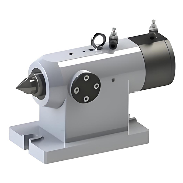
Matched with CD / WCD series precision rotary tables. It fixes workpieces via a high-precision center tip, eliminating overhang and vibration during the machining of long shaft parts.
Selection Tips
Available in two drive types: manual (HTS) and hydraulic/pneumatic automatic (TAT). Center height ranges from 110mm to 255mm, fully compatible with all table diameter specifications.
Share:
2. FT Series Pneumatic Brake Disc Tailstocks
The FT Series Pneumatic Brake Disc Tailstock is designed to provide stable support for rotary-axis setups when machining large-diameter and heavy-load workpieces. Its pneumatic braking and clamping mechanism helps improve overall system rigidity during cutting, making it a practical component for demanding machining applications.
Working as the support end of the rotary axis, the FT Series Pneumatic Brake Disc Tailstock helps stabilize the machining setup when handling large or heavy workpieces. By providing additional support alongside the main spindle end, it helps maintain workpiece stability during cutting operations where rigidity and clamping reliability are important.
When selecting an FT Series Pneumatic Brake Disc Tailstock, consider compatibility with the rotary table, the main spindle interface, workpiece dimensions and weight, mounting space, and the required support arrangement. The pneumatic supply and applicable model specifications should also be confirmed during technical evaluation.
For a suitable configuration recommendation, provide the rotary table model, workpiece drawing, workpiece weight, machine layout, and intended machining operation. These details help the engineering team evaluate compatibility and identify the appropriate tailstock arrangement for your application.
3. Hydraulic & Pneumatic Rotary Valves
Hydraulic & Pneumatic Rotary Valves are designed to transfer hydraulic pressure and compressed air to fixtures mounted on a rotary table. Installed at the center of the rotary axis, they connect stationary supply lines with rotating fixture circuits, helping prevent pipeline entanglement during table rotation. As practical rotary table accessories, they support fluid connection and fixture integration in CNC machining applications.
Installed at the center of the rotary axis, the rotary valve connects hydraulic and pneumatic circuits serving the rotary table fixtures. This arrangement allows the required pressure supply to be maintained while the table rotates, reducing the risk of hose twisting and interference with moving components.
For rotary tables equipped with hydraulic or pneumatic workholding systems, the appropriate rotary valve configuration helps accommodate fixture actuation requirements while keeping the fluid connections organized within the machine setup.
Hydraulic and pneumatic rotary valves help simplify fluid routing in rotary table systems where fixtures need pressure connections during rotation. By providing a dedicated rotary interface, they help reduce hose twisting, support a more organized machine layout, and facilitate integration between the rotary table and its workholding equipment.
They are particularly relevant to CNC machining setups that use hydraulic or pneumatic fixtures and require repeated rotary positioning without allowing stationary supply lines to become entangled with rotating components.
When selecting a hydraulic or pneumatic rotary valve, consider the rotary table model, required number of circuits, single-acting or double-acting fixture operation, working pressure, mounting interface, and available installation space. The hydraulic or pneumatic medium and connection requirements should also be confirmed before ordering.
To help determine a suitable configuration, provide the rotary table model, fixture type, circuit requirements, operating pressure, and relevant installation drawings. These details help establish compatibility between the rotary valve, the rotary table, and the connected workholding system.

4. Single Axis Intelligent Controller
The Single Axis Intelligent Controller is a dedicated control unit designed for non-linkage rotary tables. Integrating an AC servo system, it communicates with the main machine tool through M-code signals to execute precise angular indexing commands. As a functional component of rotary table accessories, it provides a practical control solution for machining setups that require rotary positioning without a dedicated CNC fourth-axis control system.
The controller coordinates the rotary table's indexing operation through communication with the main machine tool. M-code signals trigger the corresponding indexing commands, allowing the rotary table to position a workpiece at the required angle during the machining sequence.
This configuration is suitable for indexing-based machining operations in which the workpiece needs to move between predefined angular positions. It provides an alternative for compatible conventional machine tools and CNC machines that do not have a dedicated fourth-axis control interface.
The Single Axis Intelligent Controller is suitable for machining setups that require controlled rotary indexing without full simultaneous multi-axis coordination. It can be considered when upgrading compatible conventional milling machines or existing CNC equipment to support fourth-axis indexing operations.
Typical applications include multi-face machining, sequential drilling, angular milling and other processes in which a workpiece must be indexed to different positions between machining steps. The actual application depends on the rotary table configuration, machine tool control system and required machining sequence.
Before selecting a single axis intelligent controller, confirm compatibility with the rotary table, AC servo system, machine tool controller and available M-code interface. The required indexing sequence, electrical connections, installation arrangement and control signals should also be reviewed before integration.
When requesting a configuration recommendation, provide the machine tool model, CNC control system, rotary table model, required indexing operations and available interface information. These details help determine whether the controller is suitable for the intended machine tool upgrade.

5. Process Support Accessories
Process support accessories help configure rotary table systems for different workpiece geometries, clamping arrangements, and machining requirements. From L-blocks and custom bridge plates to special three-jaw chucks and cable protection components, these accessories support workholding setup and system integration for a wide range of CNC machining applications.
As part of our CNC Indexers & Rotary Tables product range, these components can be selected according to the rotary table configuration, workpiece dimensions, fixture layout, and operating requirements.
In addition to mechanical workholding components, the accessory system provides shielding solutions for power and signal cables, as well as pneumatic-hydraulic converters. These components help organize cable routing and support the integration of pneumatic and hydraulic systems within the rotary table setup.
When configuring rotary table accessories, consider the workpiece dimensions and shape, clamping method, rotary table model, fixture mounting interfaces, and machining conditions. L-blocks and bridge plates should be matched to the required mounting arrangement, while three-jaw chucks should be selected according to the workpiece and gripping requirements.
For integrated setups, also review cable protection, signal routing, and pneumatic-hydraulic connection requirements. Providing the rotary table model, workpiece drawings, fixture layout, and relevant machine interface information helps clarify compatibility and identify the appropriate accessory configuration.
Different machining applications may require a combination of workholding components, support structures, rotary connections, and control or fluid-system accessories. Rather than selecting each component in isolation, evaluate how the accessories work together within the complete machining setup.

For application-specific equipment configuration and workholding requirements, explore our CNC Machining Tooling Solutions. Contact our engineering team with your workpiece drawings, machine model, and machining requirements to discuss a suitable configuration.
Essential Machine Tool Solutions
A Premier Provider of Machine Tool & Automation Components with 20+ Years of Manufacturing Excellence.
Find by Machine Type
Find by Workpiece Type