Share
Aerospace components are rarely simple parts. Structural brackets, engine housings, turbine components, actuator parts, impellers, and precision connectors may require machining on multiple faces, at complex angles, or along curved surfaces while maintaining tight positional relationships between features.
For manufacturers using conventional 3-axis machining centers, these requirements often mean repeated clamping, additional fixtures, manual repositioning, and multiple machining operations.
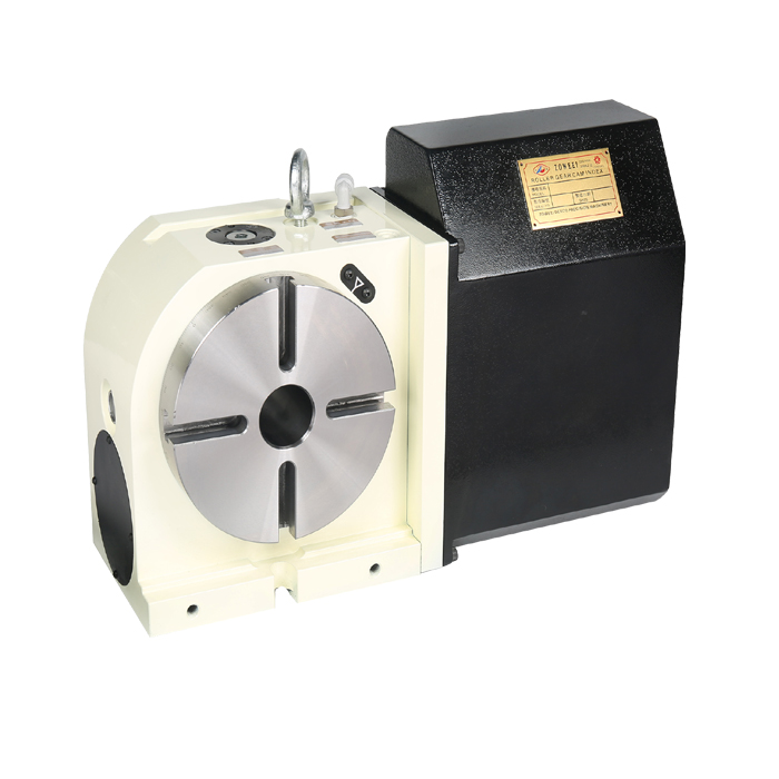
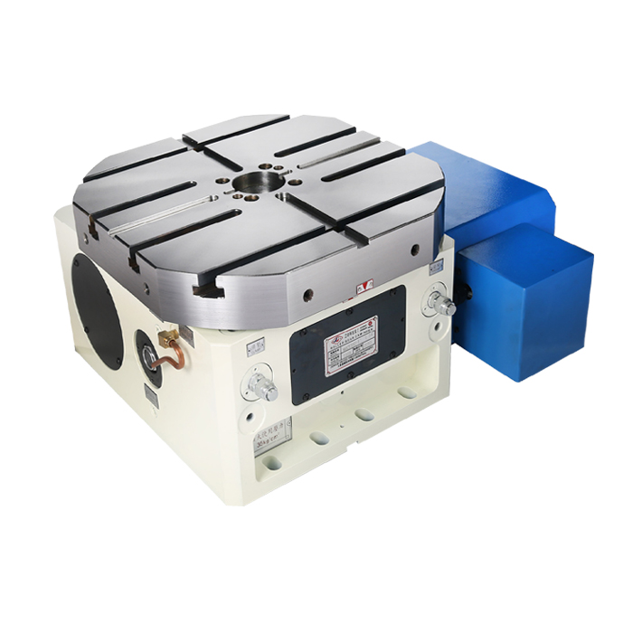
A CNC rotary table for aerospace machining provides another approach.
By adding a programmable rotary axis—or rotary and tilting axes—to a CNC machining center, manufacturers can position the workpiece automatically and machine more features in a single setup. This can reduce setup-related errors, improve access to complex geometries, and increase machining productivity.
For aerospace manufacturers, however, selecting a rotary table involves much more than choosing the correct table diameter. Positioning accuracy, repeatability, rigidity, clamping torque, load capacity, drive technology, thermal stability, and CNC compatibility can all affect final machining performance.
This guide explains how CNC rotary tables are used in aerospace machining and what buyers should consider before selecting one.
Aerospace machining combines several difficult manufacturing conditions.
Components may feature:
multiple machined faces;
angled holes and bores;
deep pockets;
curved aerodynamic surfaces;
thin-wall structures;
complex datum relationships;
high material removal ratios;
difficult-to-machine materials.
At the same time, manufacturers must maintain consistent dimensional and positional accuracy.
Repeatedly removing and repositioning a component can make this more difficult because every new setup introduces another opportunity for alignment error.
A precision rotary table allows more machining operations to be completed while the component remains referenced to the same fixture.
Aerospace rotary-table manufacturers specifically emphasize this single-setup or reduced-setup machining strategy for components such as turbine blades, blisks, structural components, and other complex aerospace parts.
Reducing setup count is one of the most important benefits of using a CNC rotary table.
Suppose an aerospace component requires machining on four sides.
With conventional machining, each setup may require the operator to:
Remove the component.
Clean the fixture.
Reposition the component.
Establish the datum again.
Verify alignment.
Clamp the component.
Restart machining.
Every time this happens, small positioning differences may be introduced.
A rotary table allows the machine to rotate the component while keeping the original workholding reference.
The result can be:
fewer manual setups;
less operator intervention;
reduced tolerance accumulation;
shorter setup time;
improved feature-to-feature consistency;
easier automation.
Multi-axis aerospace machining is widely used specifically because reducing re-fixturing helps maintain positional relationships between features while providing access to complex geometry.
Structural aerospace parts commonly include:
brackets;
frames;
mounting structures;
ribs;
fittings;
structural nodes.
Many contain pockets, holes, slots, and machined interfaces on several sides.
A rotary table enables the cutting tool to reach these surfaces without repeatedly transferring the component between fixtures.
For large aluminum structural parts, the main challenge may also involve removing a significant amount of material while controlling deformation of thin walls and ribs.
Aircraft engine components frequently require complex multi-angle machining.
Typical examples include:
engine housings;
turbine-related components;
compressor components;
bearing housings;
mounting components.
For these parts, rotary-axis positioning can improve tool access while helping maintain consistent geometric relationships.
Turbine blades contain complex aerodynamic surfaces that cannot normally be produced efficiently using simple three-axis positioning.
A tilting rotary table or five-axis machining configuration allows the cutting tool to approach the blade from continuously changing angles.
This helps maintain:
appropriate tool orientation;
smoother contour machining;
better access around the blade;
fewer fixture changes.
Blisks and impellers represent some of the clearest applications for simultaneous multi-axis machining.
Their geometry often includes:
closely spaced blades;
twisted surfaces;
deep channels;
narrow machining areas;
complex tool approach angles.
A five-axis rotary table can orient the component while the linear machine axes move simultaneously.
This enables the cutting tool to reach difficult areas that would be impractical using fixed-angle setups alone.
Electronic, hydraulic, actuator, and gearbox housings may require machining on several sides.
A fourth-axis rotary table can be particularly effective for these components because the machining is often primarily positional rather than continuously simultaneous.
Typical operations include:
drilling;
tapping;
boring;
milling;
port machining;
sealing-surface machining.
Long or cylindrical aerospace components may require rotational positioning for holes, flats, grooves, and other features distributed around the circumference.
Depending on workpiece geometry, the rotary table may be paired with:
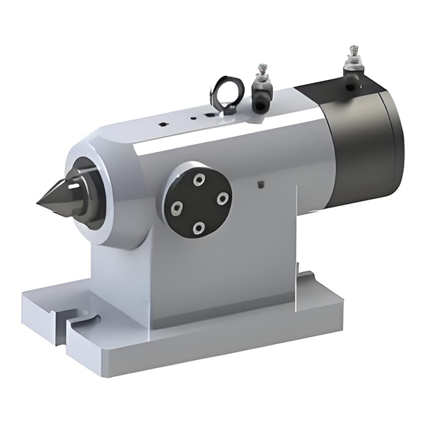
a tailstock;
steady support;
hydraulic fixture;
custom workholding system.
The complete fixture-and-table configuration should therefore be considered during equipment selection.
The material being machined affects the rotary table requirement because different aerospace materials produce different cutting forces and thermal conditions.
High-strength aluminum alloys are widely used for aerospace structures because of their favorable strength-to-weight ratio.
Compared with titanium or nickel-based alloys, aluminum generally allows higher material removal rates.
The rotary table therefore needs sufficient:
rotational speed;
acceleration;
bearing rigidity;
fixture stability.
For production machining, reducing indexing time between faces can significantly affect overall cycle time.
Titanium alloys such as Ti-6Al-4V are widely used in demanding aerospace components.
Titanium machining presents greater challenges because cutting conditions can generate high localized heat and significant cutting loads.
For the rotary table, this means buyers should pay particular attention to:
structural rigidity;
clamping torque;
bearing capacity;
workholding stability;
thermal behavior.
Current aerospace machining guidance consistently identifies machine rigidity, stable fixturing, thermal control, and tool-access strategy as important when machining titanium components.
Nickel-based heat-resistant alloys are commonly associated with high-temperature engine applications.
They can generate demanding cutting conditions and relatively high machining loads.
For these applications, simply choosing a rotary table with good positioning accuracy is not enough.
The table must maintain position while cutting forces are applied.
This makes static and dynamic rigidity, clamping performance, and bearing design particularly important.

Consider two rotary tables with similar published positioning accuracy.
Table A has excellent angular positioning but relatively low locking rigidity.
Table B provides comparable positioning accuracy but substantially stronger structural and clamping performance.
During light positioning operations, both may perform similarly.
During aggressive titanium milling, the result may be very different.
Cutting forces can expose weaknesses that do not appear in unloaded accuracy specifications.
For aerospace buyers, the evaluation should therefore include:
Positioning Accuracy + Repeatability + Rigidity + Clamping Torque
rather than accuracy alone.
It may seem safer to purchase the largest available CNC rotary table.
However, oversized equipment can introduce disadvantages:
greater rotating mass;
higher inertia;
slower acceleration;
greater machine-space requirements;
higher purchase price;
possible interference with machine travels;
reduced available machining envelope.
The correct rotary table should be sized according to:
Part Envelope + Fixture Envelope + Load + Moment + Cutting Force + Machine Space
—not simply workpiece diameter.
Some aerospace components require long machining cycles.
During these cycles, temperature changes can affect:
machine structure;
spindle;
rotary-table bearings;
drive mechanism;
encoder system;
workpiece.
A rotary table that performs accurately when cold should also remain stable after extended operation.
Long-cycle aerospace machining therefore requires attention to both mechanical accuracy and thermal behavior. Contemporary aerospace machining guidance identifies thermal stability as a major consideration for maintaining dimensional consistency during extended cutting operations.
For demanding applications, buyers should ask manufacturers how rotary-axis accuracy is controlled under continuous operation.
A 250 mm table from two manufacturers may have very different:
load capacities;
bearing systems;
clamping torque;
positioning accuracy;
drive designs.
Diameter alone says little about actual machining capability.
Published positioning accuracy is important, but aerospace machining also depends on:
rigidity + repeatability + clamping + thermal stability
A table that positions accurately but deflects under cutting load may still produce poor results.
Buyers sometimes calculate table capacity using workpiece weight alone.
The fixture, chuck, adapter plate, and clamping components must also be included.
Maximum static load does not indicate how quickly the table can accelerate a large-diameter fixture.
Production applications should evaluate inertia and cycle requirements.
If a component only requires machining on several fixed faces, a fourth-axis table may provide the required productivity at lower cost and complexity.
Before ordering, confirm the controller, servo system, electrical interface, machine space, and available axis capability.
The value of a rotary table should not be measured only by its purchase price.
Consider the broader machining process.
A rotary table may reduce:
manual setup time;
dedicated fixture requirements;
work-in-process movement;
operator intervention;
re-alignment time;
setup-related dimensional variation.
It may also increase the number of machining operations completed during one machine cycle.
Therefore a better evaluation is:
rather than:
For repeated aerospace production, reducing several minutes of setup or indexing time per component can become significant across hundreds or thousands of parts.
A CNC rotary table is worth considering when your current process regularly involves:
manually rotating components;
machining several sides of the same component;
producing angled holes or features;
using multiple fixtures for one part;
repeatedly re-establishing workpiece datums;
machining cylindrical components around their circumference;
producing complex aerospace geometries.
If these operations are common, adding a fourth or fifth rotary axis may improve both productivity and process consistency.
A CNC Rotary Table for aerospace machining is more than an accessory for rotating a workpiece.
Properly selected, it becomes an integral part of the machining process by allowing manufacturers to produce multiple surfaces and complex features with fewer setups.
For simpler brackets, housings, shafts, and multi-face components, a 4-axis CNC rotary indexing table may provide an efficient solution.
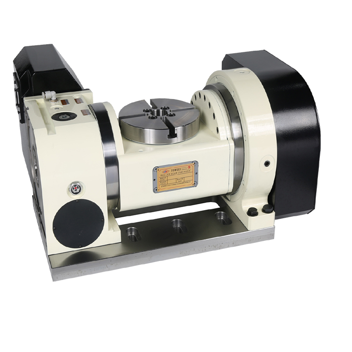
For turbine blades, impellers, blisks, and other complex aerospace geometries, a 5-axis tilting or trunnion rotary table may provide the additional freedom required for continuous multi-axis machining.
The most important purchasing decision is therefore not:
“What size rotary table should I buy?”
It is:
“What rotary-axis configuration can handle my workpiece, cutting forces, accuracy requirements, machining strategy, and existing CNC machine?”
For aerospace applications, buyers should evaluate at least:
accuracy, repeatability, rigidity, clamping torque, total load, moment load, workpiece inertia, drive mechanism, thermal stability, machine clearance, and CNC compatibility.
A rotary table selected around these real machining conditions is far more likely to deliver stable performance than one selected from diameter and price alone.
There is no single best configuration. A 4-axis rotary indexing table is often suitable for multi-face brackets, housings, cylindrical parts, and drilling applications, while a 5-axis tilting or trunnion table is better suited to blades, impellers, blisks, and complex contour machining.
They allow multiple surfaces or angles to be machined while the workpiece remains in the same fixture. This can reduce manual setups, preserve datum relationships, and improve machining efficiency.
No. Many aerospace housings, brackets, actuator parts, shafts, and structural components can be machined efficiently with 3+1 or 4-axis indexing. Full five-axis machining is most useful when geometry or tool access requires two rotary degrees of freedom.
In 3+2 machining, the rotary axes position the part and then remain stationary while X, Y, and Z perform the cut. In simultaneous five-axis machining, rotary and linear axes move together during cutting.
Rigidity, clamping torque, load and moment capacity, positioning repeatability, bearing stability, and thermal behavior are particularly important. Titanium machining can create demanding cutting conditions, so table stability under load should be evaluated rather than focusing on positioning accuracy alone.
Often yes, provided the machining center has sufficient physical space, table load capacity, CNC-axis capability, servo compatibility, and electrical or hydraulic interfaces. Machine and controller information should be verified before ordering.
Direct drive can be advantageous for high-speed positioning and simultaneous multi-axis motion because it eliminates conventional mechanical transmission stages. However, worm-drive and roller-cam tables may be more appropriate for applications prioritizing torque, rigid indexing, or cost efficiency.
Send the component drawing or 3D model, dimensions, total workpiece and fixture weight, material, machining operations, required accuracy, expected cutting load, required indexing speed, desired machining mode, machine model, CNC controller model, and installation orientation. This allows the supplier to recommend the rotary-table configuration based on the real machining application.